
John R. Bentley 2011.
Completing
However there are a few things to be done first. I have left the machining of the D-valves to the end. These are the last of the parts requiring machining for this engine detailed on the drawings. Next the gaskets will be cut and packing added to the glands. Then the fit and clearances of all those metal parts which are dependant on cumulative gasket thickness will be determined and adjusted accordingly. At that point this engine will be ready for testing and running during the break-in period. Final jobs such as insulating, adding lagging sheets and painting will be carried out and the machine will be partially dismantled for these procedures.
I was always under the impression that a slide valve was held against the port face by the existing pressure in the steam chest. I can't fathom the suggested design using a 0.125" rod passing through a 0.125" hole in the valve. Theoretically it requires perfect alignment between the hole, valve rod, gland, guide, valve face and port face from the outset and leaves absolutely no provision for normal valve wear.
The only actual physical pieces remaining to be fashioned are optional and consist of part of the cylinder insulation. Some builders prefer this to be composed of vertical strips of a rich wood held in place by polished brass strapping top and bottom. Others prefer metal cladding sheets over cylinders either lagged with fibrous material or in small models simply covering the air space. This metal can either be made black or "blued" by heating or painted to protect against corrosion. I don't know what I will do.
Here are the finishing touches to the engine:
This background is Oxford Blue on a properly adjusted monitor
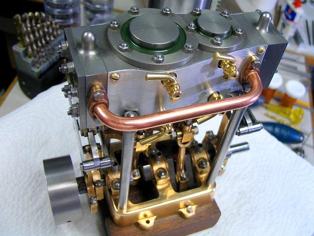
This engine has turned out to be quite powerful (as I had hoped), certainly an equal to the Twin Launch version. Present tests have been tried with compressed air at up to 75 PSI. I think that steam at 115 PSI with a condenser might yield a remarkable power output from such a compact engine.
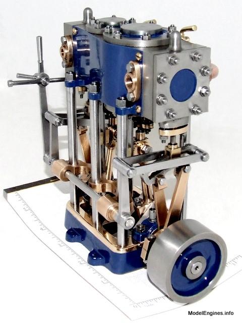
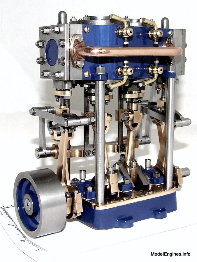
The Stuart Compound Launch Engine in Oxford Blue
Engine Construction Pages:
and
Erecting the Stuart Compound Launch Engine
- prior to steam testing -
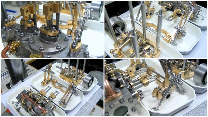
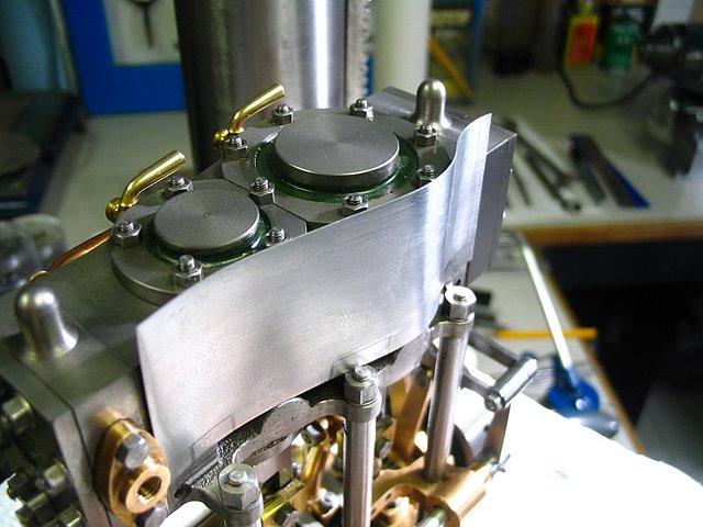
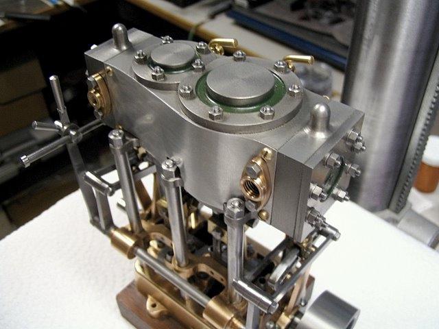
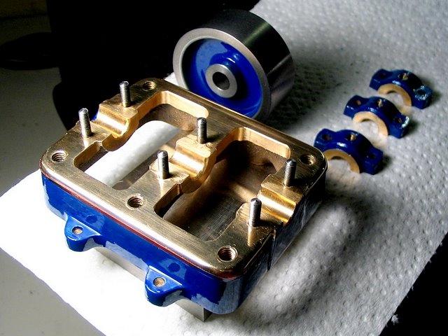
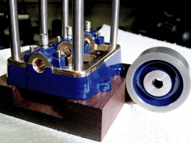
Views of the three basic assemblies which will be further dismantled and made ready for final fitting
Of course as the engine is put to work, I may design and attach pumps, valves, condenser, other piping, couplings and linkages - all of a custom nature.
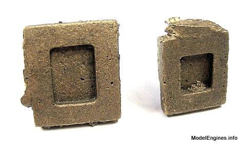
These are the raw castings for the valves

The valve faces before finishing
The only milling cutter that I can get to work properly with gunmetal!
.JPG)
This metal performs very well in the lathe - but it certainly can misbehave in the mill...
You can tell when the finish is getting better if the valve
sticks on the valve face - just from atmospheric pressure!
.JPG)
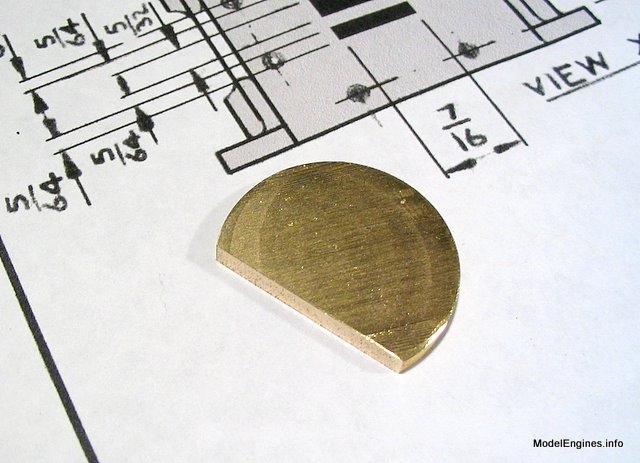
The LP valve
A near-mirror finish on the valve surface
The valve and port faces will come to their own agreement after a few hours of running
.JPG)
A piece of Naval Brass to make the valve adjustment pieces
Tapping a valve adjuster

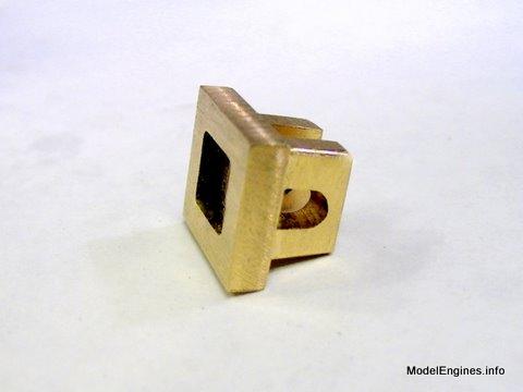
The valve with the rod threaded into the adjuster for the HP valve chest
(note that I have made the hole in the valve elongated instead of round as in the drawings)
.JPG)
If all the smart people in the world still can't produce perfect piston/cylinder fits that are impervious to wear without the use of spring-loaded piston rings, by what leap of faith can anyone expect the dimensions of a D-valve to be any better? OK - of course it can be done, even in such a small model - but should it? If allowing no room for error is such a great idea, have a look sometime at the valve design in Stuart's own No.10 engines...
The LP steam chest and valve
.JPG)
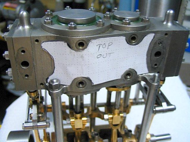
Gasket material and valve cover

Gasket outlined by rubbing a thumb over the cover edges
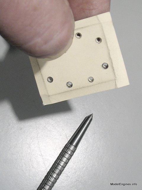
The holes were cut by twirling the tip of the punch hard against
the edges of the untapped holes in the cover underneath
Trimming the outside

Checking it out
The extra hole in the gasket behind the front right stud is for the reversing lever bracket screw

Marking out the gasket centre opening
.JPG)
Punching the corner holes
.JPG)
Cutting between the holes
(top middle hole is for reversing lever bracket)
.JPG)
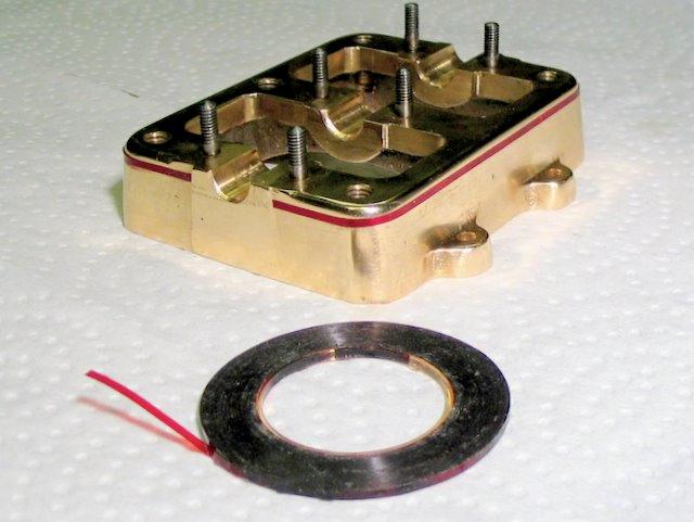
A finished gasket in position under the LP steam chest
.JPG)
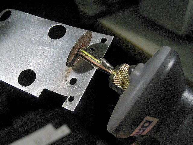
Cutting cylinder holes in the top gasket
.JPG)
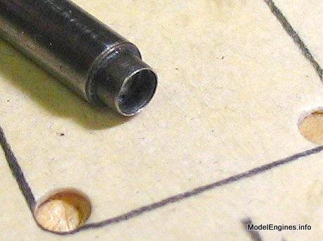
The small holes were only marked with the large punch to avoid damaging the threads
they were punched with the small homemade 7BA-sized punch seen below:
The Silver Steel punch is about 1.5 " long and cuts No.37 holes
Ready to cut around the covers
.JPG)
Cutting away...
.JPG)
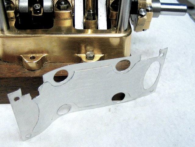
Finished top gasket in position
.JPG)
The view after soaking the gasket in No.20 motor oil, but prior to covering
the gasket on both sides with heavy steam oil during assembly
.JPG)
My concern for the moment is to fit everthing together which is required for testing. When that hurdle is passed, I will turn my thoughts immediately to the appearance of the model. I intend this model to represent a marine engine of some sort, whether in a boat or simply for working display. It may even serve as part of an alternate steam plant for my aluminum tugboat to compare the relative merits of the Stuart Twin vs. the Stuart Compound for model boat work.
Fitting everything together consists of innumerable small jobs - many of them delicate operations done by hand. These are tasks demanding skill, good eyesight and a clear mind. Since I don't have as much of any of those as I'd like, there wasn't enough of me left to try to be a photographer at the same time. Consequently I have little to show. The best I can do is to tell you that it is slow and tedious work which so far has spanned most of a week. The fitting work is part of the assembly process and every bit as much part of the construction process of the Compound Launch as the plain machining of the castings and stock. Time should be allocated for fitting, adjusting and break-in - I have expected all along that it will be a month before I am satisfied that the job is done. I have no indications that I should alter that prediction.
The Compound is more difficult to set up with the reverse gear than the twin (which uses the identical gear). You can set it up by theory and the engine might even run, but it is hard to be sure exactly what is happening inside, since the exhaust steam of one cylinder runs the other cylinder. It is a time to be watchful where you put your fingers - an open frame engine with this amount torque can do some very unpleasant things to a digit that gets in the wrong place.
Very thin aluminum that I am using to make the cylinder insulation lagging sheets
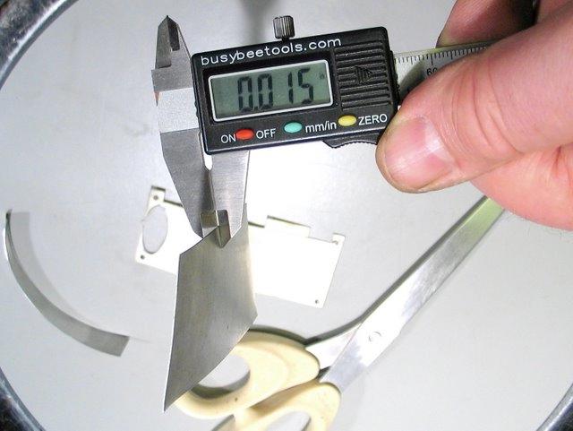
This metal is available by the roll from hardware stores
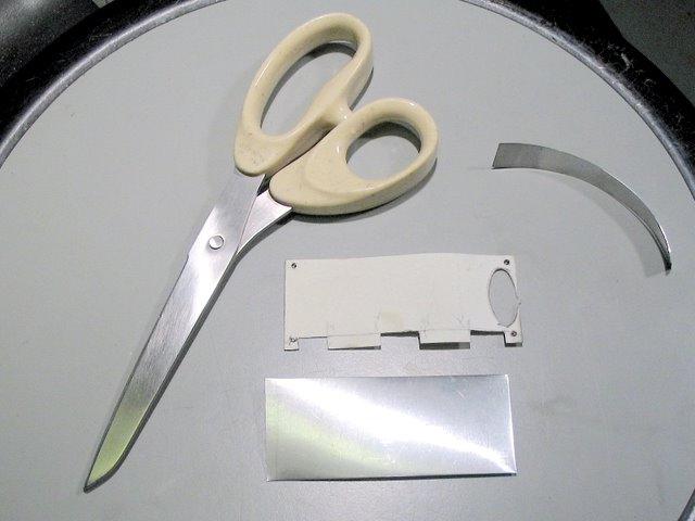
Paper patterns are the only easy way to get the correct outline
An initial test fit of the curves
I bent the curves around these pill bottles

The surplus at the top has been trimmed off
next - making the lug cut-outs (with a rotary tool and side cutters)

This lagging sheet is fitted into position - now to the other side...
The pattern traced out on the aluminum sheet (forground)

A small round file using a drill chuck as a handle to make holes for the drain cocks

Dremel in action cutting out for a steam flange
It appears to fit well
The plans specify a slightly wider steam chest than cylinder block
to ensure a flush joint between the chest and lagging sheet
I used thin metal to obtain this flush joint, so I must bolster the strength of the lagging sheet from behind
Cutting a pattern of the inner space for the lagging sheet stiffeners
Three layers of aluminum tape adhere to the back to stiffen the lagging sheet material
OK! I have made enough green, red, gray and maroon engines -
...this one's going to be Oxford Blue!

It is hard to photograph such a powerful hue and make it appear correct on everyone's monitor. Whether my paint is accurate, I can't be sure - reflection and absorption by the tints contained in paints are influenced greatly by the nature of the light.
Trivia:
According to the University of Oxford website, they recommend that the worldwide recognized colour for their brand be created on computer monitors by the hexadecimal code #002147 in HTML, or as RGB by 0 Red, 33 Green, 71 Blue. The process colour is 100% Cyan, 80% Magenta, 0% Yellow, 60% Black.
Graphic arts striping tape used for masking the soleplate
My, my, my!
Don't worry - the colour will be better after it dries!
I left the sides of the bearing caps unpainted as all but the two ends act as thrust bearing surfaces
(and the end ones don't show)
"as interesting as watching paint dry..."

Here's better colour!
The back side of the engine is visible here, but when installed in a steam plant, much of this view
would be obscured by the air pump, feed pump, condenser, valves and piping
The next steps will be to test the engine on a conservatively fired, non-flash monotube boiler and eventually with a condenser and hot well. I hope to add a simpling valve for starting and perhaps a crosshead-operated air pump. I will likely locate the feed pump at the front of the engine as a shaft-driven accessory.
June 20, 2011.
Castings, Materials and Fastenings
Soleplate
Cylinder Block
Top Covers
Bottom Cylinder Covers
Steam Chests
Crosshead Guides and Bracket
Crankshaft
Eccentrics
Flywheel
Connecting Rods and Crossheads
Main Bearings
Pistons
Fittings: Oil Cups
Fittings: Drain Cocks
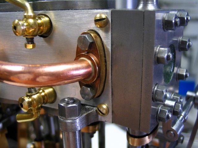
Fittings: Exchange Pipe, Flanges and Glands
Stephenson Link Reversing Gear (5 pages)
Preparing and Erecting the Engine - this page
or
Compound Launch main page
Main website home page ModelEngines.info
![]()
© John R. Bentley 2011.