John R. Bentley 2011.
Constructing a
There are twenty-six unique parts required to make the Stuart Compound Launch a reversible steam engine. The reverse gear used to be sold as a separate kit, but at this writing (May 2011) the materials and castings for the Stephenson Link have been included with the engine castings sets for some time.
The reversing gear for this engine consists of 26 separate pieces not counting the fasteners. In most cases there are more than one of a particular component, so it will not be necessary to include pictures of every actual part, but only one example of each type. Seven castings were provided - the remaining parts are to be made from supplied materials. I will start with the construction of the expansion links and dies, then valve rods and heads.
A one-eighth inch
The English system of using two-view drawings and avoiding marking duplicate dimensions creates the necessity for deriving numbers which are unmarked on the individual component views (either from the given dimensions or from drawings for other mating components). This system works well for those intimately familiar with the practice, but some might find it safer to draw sketches of certain components with everything marked to avoid making an error.
I have drawn an example of a simple stand-alone working sketch:
Of course in the "old days" we could scale from drawings, but I am using plans for the reversing gear which I purchased from Stuart Turner in the 1988. They are not full size and I am not prepared to trust the accuracy of the scale of ANY drawings after reduction.
Engine Construction Pages:
Stephenson Link Reversing Gear
- for the Stuart Compound Launch Engine -

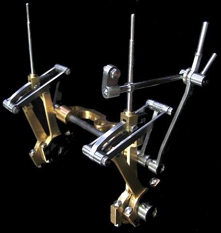
The complete set of reverse linkage and eccentrics
On this model I have chosen to add a locking handle to the hand lever, making twenty-seven separate components to be constructed. In addition five of these are made up from multiple pieces, adding six more to the parts count. There are just over forty threaded fasteners (some of which may require minor modification during fitting) and three silver steel pins to cut to length. All in all, there is a fair bit of time needed to complete this portion of the engine.
Page One:
(of 5)
The Expansion Links
Expansion link
A coating of toolmaker's ink from a spray can
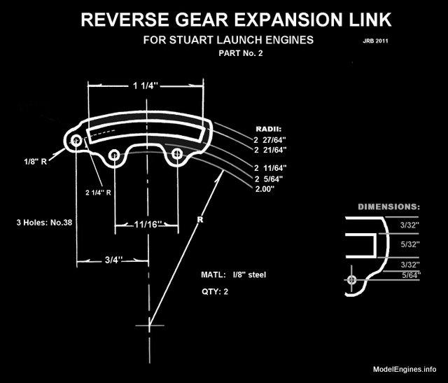
The maximum radius is 2 21⁄64" - so I clamped the plate to a piece of wood to locate the centre

Click Here for PDF
The expansion link is simply three pivot holes and a curved slot surrounded by metal
Marking out the other expansion link on the same plate
Clamped in the 4-inch rotary table ready to cut the slot and to profile the top edge
I cut a 1/8" groove centered in the 5/32" wide marked slot
Chain drilling in the groove with a 1/8" bit
The holes were joined with a 1/8" endmill
Slot widened to the full 5/32" as required and top edge chain drilled
Top edge finished and note that I have "marked out" more of the outline with the endmill
Time to work on the second link (while there is still enough metal to hold the plate)
That is all the machining I will do to this piece in the rotary table
(but some might prefer to finish the job there, by screwing the piece to a sacrificial plate)
I get a lot of use from my 4"x6" horizontal/vertical bandsaw
A business card underneath allows the plate to slide over the table smoothly
Notching out to remove as much metal as practical
This is a time to be careful with fingers!
That is as close as I can safely come to the line
A coarse round file will do wonders in this soft steel
What the file won't accomplish, the Dremel will!
The end must match 1/4" bosses on the drag links, so I curved around a hardened steel pin held in the vise
That is a Dremel sandpaper drum held in a ER-16 collet on the Taig mill
Essentially that's the job - any additional finishing can be done during final assembly of the engine
Size reference
A simple way to mark out the second piece with spray ink on the smooth back side of the plate
I scored around the upper link since there could be (was!) some underspray or ink seepage
The pair of finished expansion links
I can set them aside and make the 1/4" wide curved dies to fit the slots
The expansion dies will be cut from leftover 1/8" plate from the links
The two units are being made together and each requires one No.40 hole
Chain drilled as before
The two dies will be cut from this piece (lower) and centered about the holes
Insuring that it slides in the slot
Checking out the finished dies in the expansion link slots
The next job will be the valve rod heads - made from this piece of brass milled to 1/4" x 9/32"
Centered in the Taig 4-jaw chuck
Drilling No.37 in preparation for tapping
Tapping 5BA for the valve rod
Parting one of the the valve rod heads to length to length
Milling the 1/8" slot with a 1/8" 2-flute endmill
Checking the fit around the expansion link in situ
A simple way to avoid damage when using the punch on this component
Drilling for a 7BA thread
Opening out one side with a clearance drill
Hand tapping the far side - using the clearance hole as a tapping guide
A 5BA nut and bolt used as a convenient handle
The corners have been rounded with a file - this valve rod head is complete
(I find it easiest to do this with a flat file while holding the part in my hand)
Marking the threaded valve adjustment section of a stainless steel valve rod
Turning down the rod guide section in steps
Cutting the 5BA threads for the adjustment section
The two completed valve rods
The rods have been polished and the thread crests flattened with a file in the lathe to retain a diameter of .125"
The tips are rounded with a file to ease entry into the valve guide bores at the tops of the steam chests
I will update this page as more work on the reversing gear continues...
Eight reverse gear parts were completed on this page...
Eccentric sheaves and shaft bracket were finished earlier...
Fifteen reversing parts to go - this is fun!
After that it is on to the making the valves and lagging sheets
Next Page Making the Drag Links
Castings, Materials and Fastenings
Soleplate
Cylinder Block
Top Covers
Bottom Cylinder Covers
Steam Chests
Crosshead Guides and Bracket
Crankshaft
Eccentrics
Flywheel
Connecting Rods and Crossheads
Main Bearings
Pistons
Fittings: Oil Cups
Fittings: Drain Cocks
Fittings: Exchange Pipe, Flanges and Glands
Stephenson Link Reversing Gear (this page)
Stephenson Link Reversing Gear (page 2)
Stephenson Link Reversing Gear (page 3)
Stephenson Link Reversing Gear (page 4)
Stephenson Link Reversing Gear (page 5)
Completing and Erecting the Compound Launch Engine
or
Compound Launch main page
Main website home page ModelEngines.info
![]()
© John R. Bentley 2011.