
John R. Bentley 2011.
Constructing the Reversing Gear (page 4):
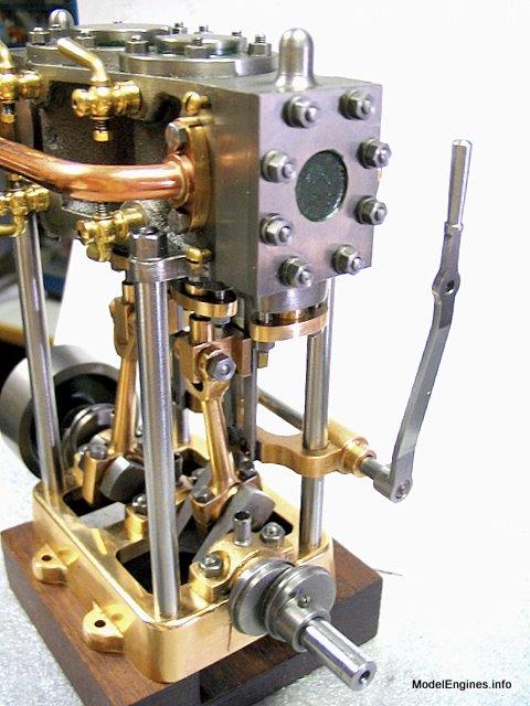
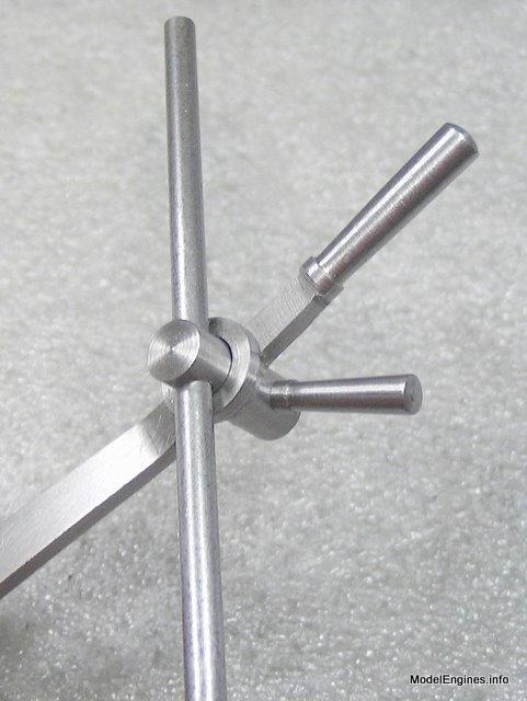
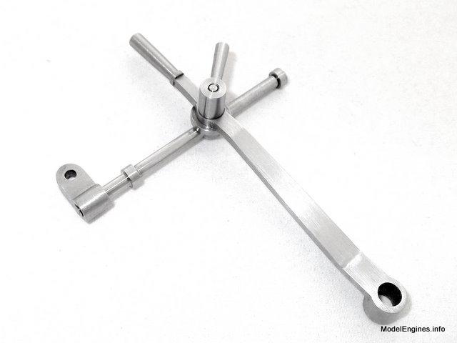
As you can see the lever has a hand grip at the top and slides along an anchor rod with small collars which act as limit stops. There is a hub at the bottom of the lever which fixes to the reversing shaft and also a locking handle near the top to hold the lever in any position along its travel. One end of the anchor rod has a simple bracket which will pivot on the high pressure steam chest cover to accomodate movement through an arc.
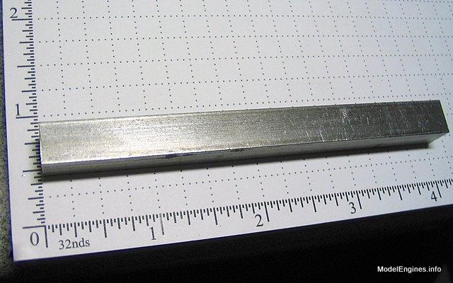
A four-inch length of bar was supplied to make the lever
Engine Construction Pages:
the Reversing Lever et al
- for the Stuart Compound Launch Engine -

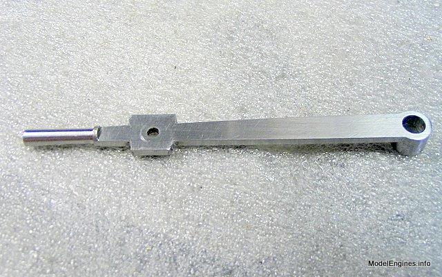
Bottom view of the reversing lever with locking handle, anchor rod and bracket
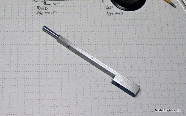
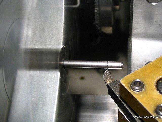
Offset turning in the four-jaw chuck to form the hand grip
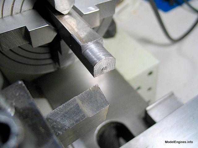
The grip is machined along the bottom of the bar stock to allow making the wide hub at the other end of the bar

The finished shape of the grip

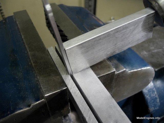
Removing some metal from the bottom of the bar as required on the plan
I cut away excess metal with a hacksaw to save excessive milling
After milling the previously-hacked surface flat
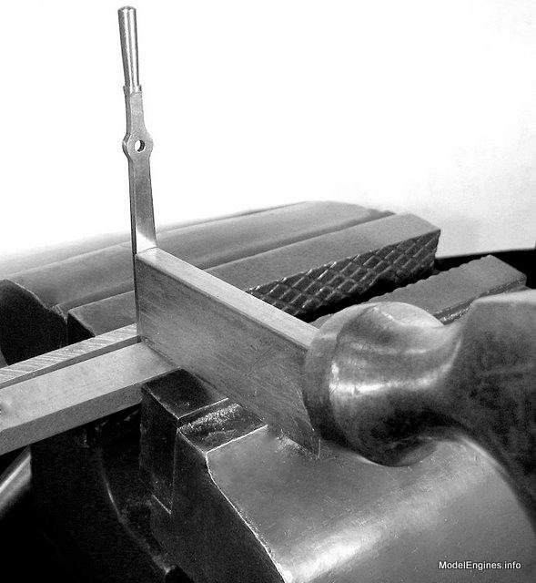
Forming another hub

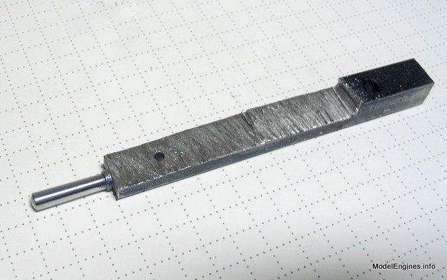
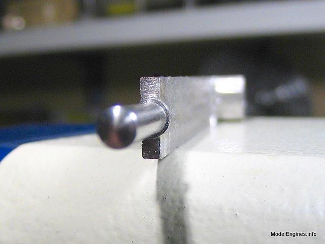
This shot shows that the lever's bar will be thinner than the grip
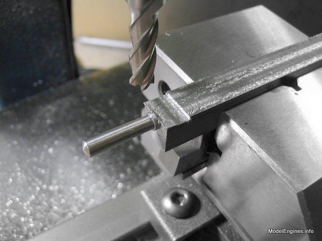
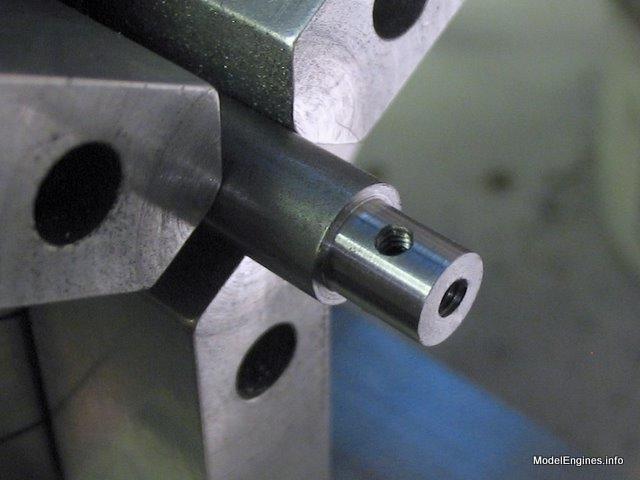
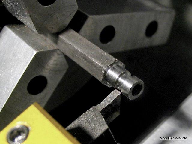
Reaming the hub bore 3/16" for the reversing shaft

I have left some metal - as the profile will be circular around the upper hole
Here is a view of the other side showing the hub more clearly

Milling the round area
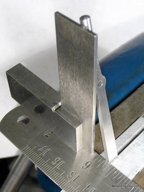
In the vise for a couple of clouts (a one-quarter inch offset is required)
Isn't this a great picture! - it reminds me of one of those old textbook photos from when I was a mere boy :-)
Checking the amount of offset
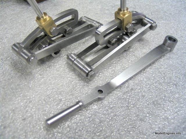
The finished lever beside the products of previous pages
Just a shot to show the reversing lever in position
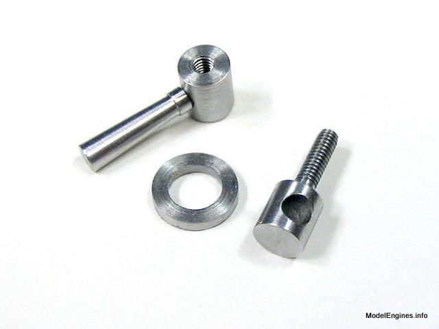
Threading the anchor rod guide 7BA for the locking handle
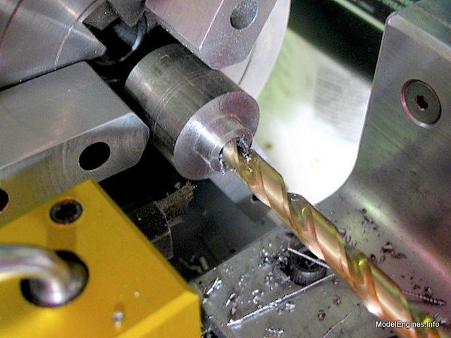
Drilling the guide 1/8" to accomodate the anchor rod
Making the locking washer
I decided to add a locking handle instead of the simple thumbscrew called for in the plan. This is the handle hub.
Here is macro view of the handle
At higher power (through the Lomo microscope) you can see that the threading needs to be relieved at the shank
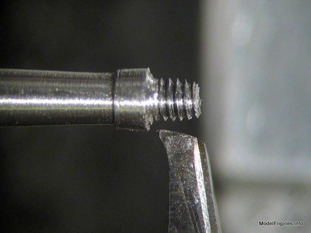
I just used a tool that was nearby to cut away a little excess metal
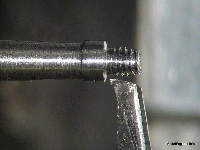
Here are the small parts just made in the above photos
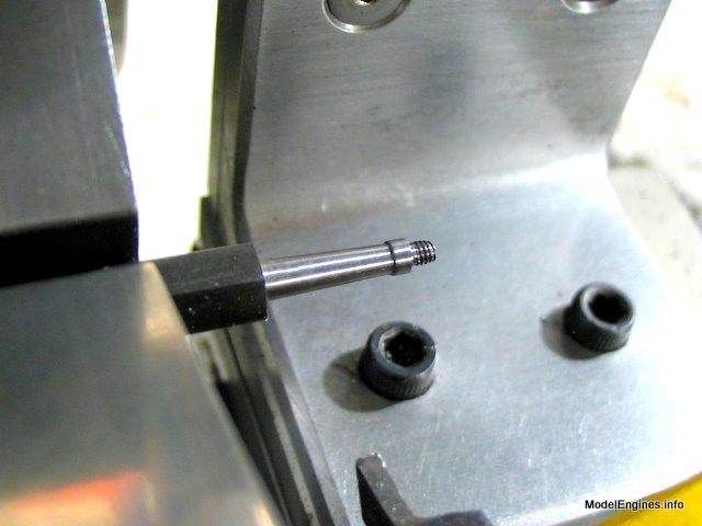
A trial fit on the unfinished anchor rod
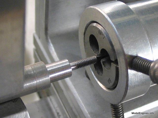
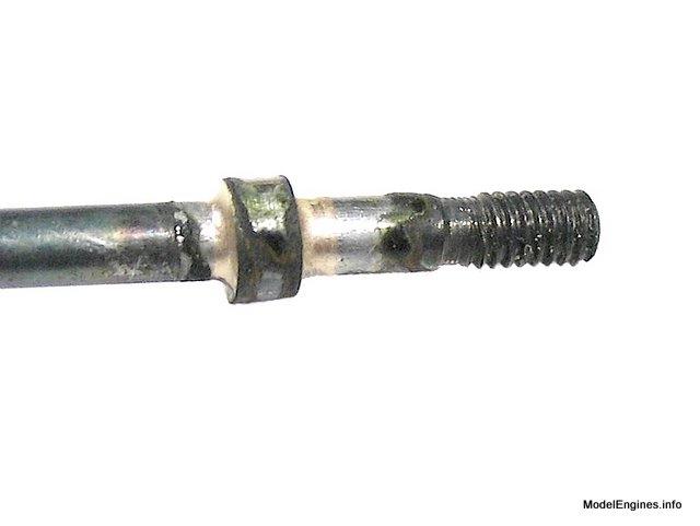
Preparing one end of the rod for a 5BA thread to screw into the bracket
Making the collar stops
In preparation for silver brazing I tied iron wire around to prevent the collar from travelling aimlessly

After the brazing...
Well...a little bit of Duffy's polish didn't hurt one bit!
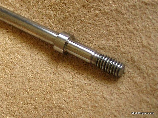
(Duffy sent me a tube of Maas concentrated creme polish - all I can say is, Wow!)
This is not a big object

There was no instruction about attaching either of these collars - so I threaded the other one on the outer end

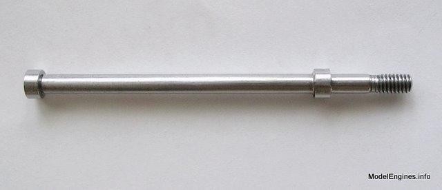
The completed anchor rod
The final part is the bracket - I'm making it from a piece of 1/4" keystock

The end hole will be threaded, the pivot hole will be clear

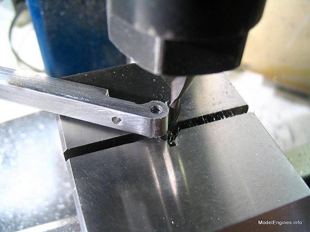
Milling the flat portion of the bracket

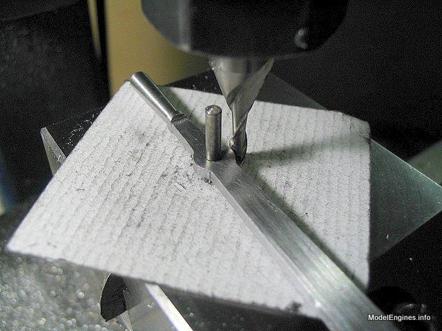
Making the round bit by swivelling on a pin (short and hence not visible)
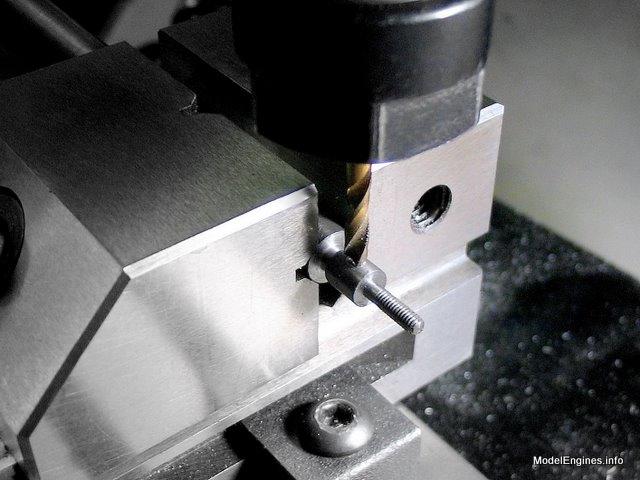
Tapping the bracket 5BA to match the end of the anchor rod

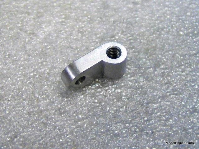
The finished bracket
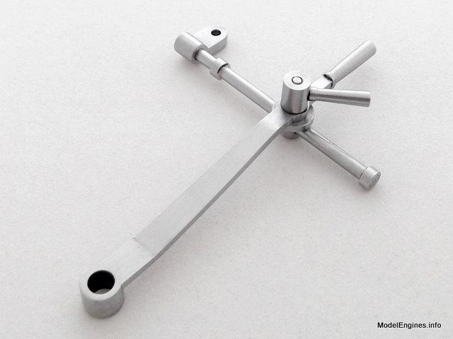
Here are a couple of shots of the completed lever assembly
It seems that if you buy the Double 10V engine they supply a casting for a similar lever
but on the launch engines we are expected to make it from scratch :-)
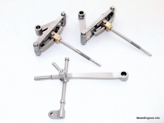
Here is everything completed to date (except the eccentrics which were done last year)
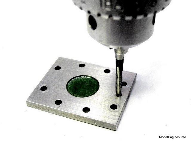
The final coup: tapping the Steam chest cover for the bracket
A 7BA bolt serves as the anchor rod pivot - it screws into the cover and butts against the steam chest underneath
(of course the double washers under the nuts are temporary until the steam chest gaskets are in place)

Next Page
The machining of the eccentric straps/rods from gunmetal castings
Castings, Materials and Fastenings
Soleplate
Cylinder Block
Top Covers
Bottom Cylinder Covers
Steam Chests
Crosshead Guides and Bracket
Crankshaft
Eccentrics
Flywheel
Connecting Rods and Crossheads
Main Bearings
Pistons
Fittings: Oil Cups
Fittings: Drain Cocks
Fittings: Exchange Pipe, Flanges and Glands
Stephenson Link Reversing Gear (page 1)
Stephenson Link Reversing Gear (page 2)
Stephenson Link Reversing Gear (page 3)
Stephenson Link Reversing Gear (page 4) - this page
Stephenson Link Reversing Gear (page 5)
Completing and Erecting the Compound Launch Engine
or
Compound Launch main page
Main website home page ModelEngines.info
![]()
© John R. Bentley 2011.