
John R. Bentley 2011.
Constructing the Fittings (page 3):
In the scheme of the overall engine this pipe is more than just a conveyance for steam to pass from one cylinder to another...
The exchange pipe is one of three volumes within this engine that together make up the receiver. The other
two spaces are: (1) the exhaust passages leading from the (small) high pressure cylinder and (2) the low
pressure steam chest. In the Stuart Compound Launch engine this total receiver volume is equal to the
the full volume of the HP cylinder - which is 0.39 cubic inches. The low pressure cylinder volume
is 2.77 times larger - 1.08 cubic inches.
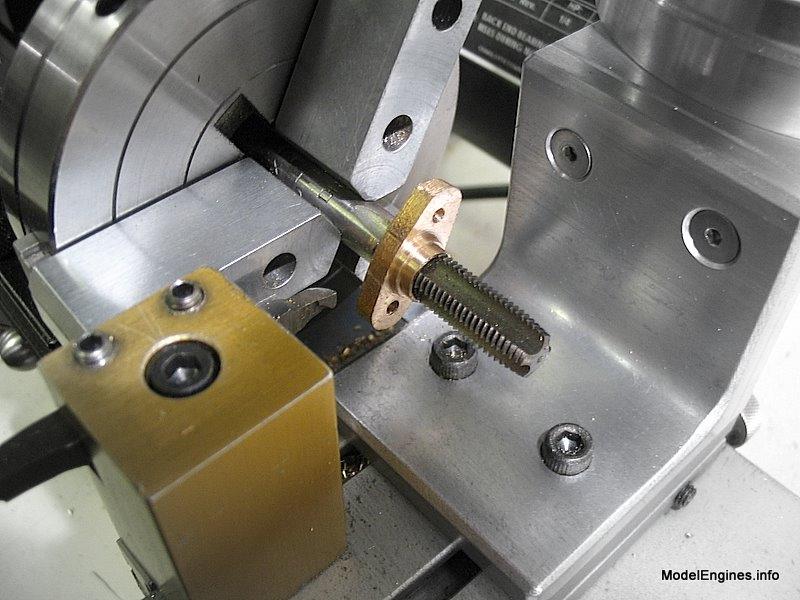
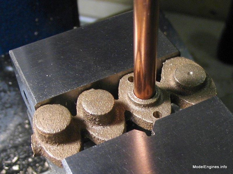
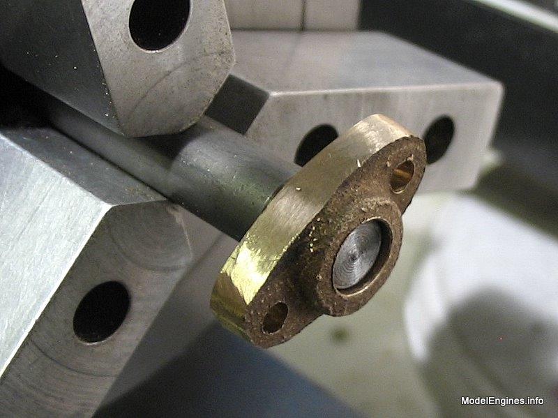
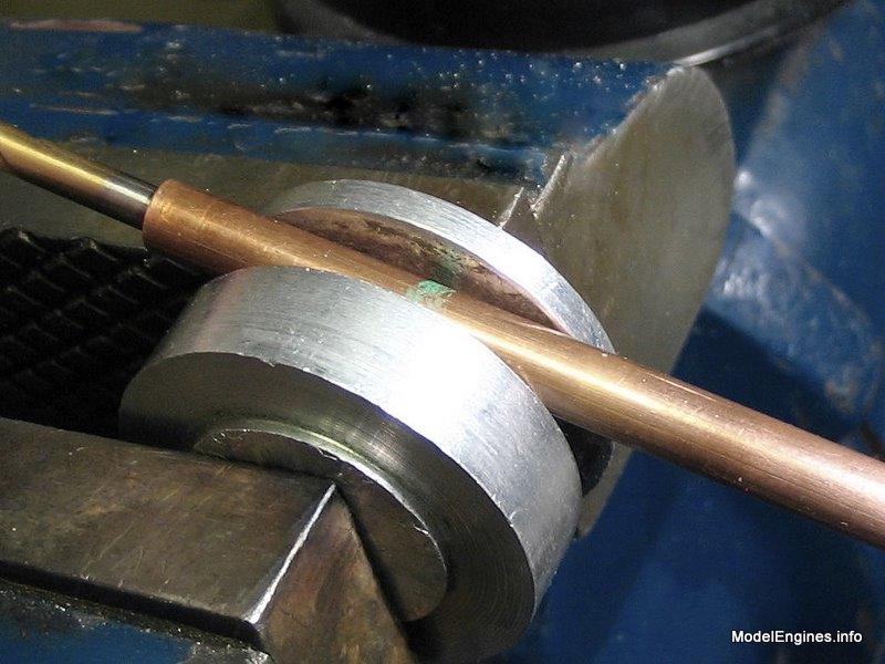
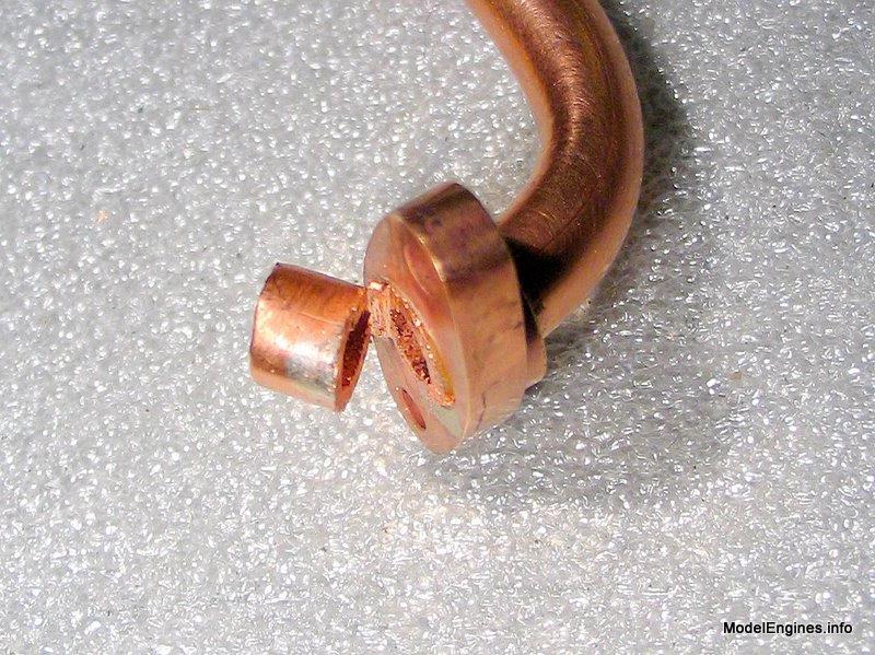
Below:
A rod has been inserted on the left to get a purchase on the short end. A rounded end on the rod will help reduce local deformation as it tries to "poke through" the side of the tube wall.
There are four glands required for this engine - two on the pistron rods and two on the valve rods. Their function is to compress the graphite yarn material inside the packing boxes to provide a steam tight seal around these reciprocating rods.
Flanges, Pipework and Glands
- for the Stuart Compound Launch Engine -

This section covers the construction of the steam pipe flanges,
the exchange pipe between cylinders and the four packing box glands.
The Pipe Flanges:
I started with the largest flange which is designed to connect a 5/16" exhaust pipe to a condenser
I made this one from a partially machined casting left over from my Stuart Twin launch engine
(this would allow me one spare casting - just in case)
Drilling the mounting holes

Flakes of gunmetal!
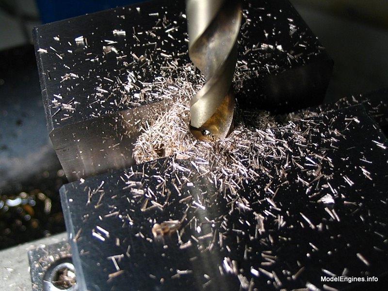
Drilling through in preparation for tapping

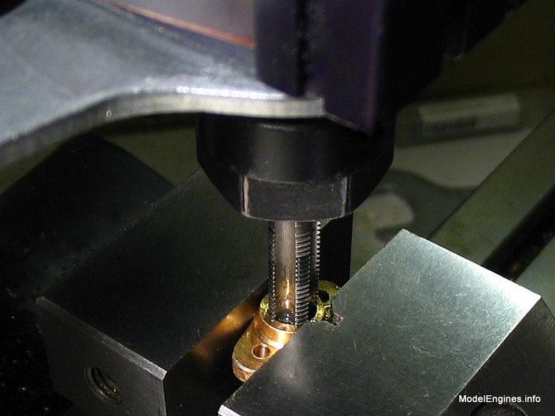
Tapping 5/16" x 26 TPI by hand in the Taig mill
(note the large flat metal wrench at the top that I used to turn the spindle by its hex section)
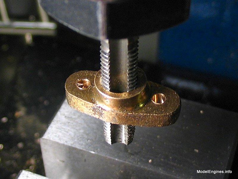
To remove the flange it is easier to loosen the vice, crank up the mill head and unscrew it from the tap by hand.
This is easier than trying to follow the thread pitch with the Z-axis crank while turning the spindle in reverse
Don't ever do this
- my excuse is that I have soft aluminum jaws in the chuck and the tap is very large and sturdy :-)
This is a good opportunity to face the top and bottom parallel to each other
(and perpendicular to the axis of the thread)
The completed exhaust flange
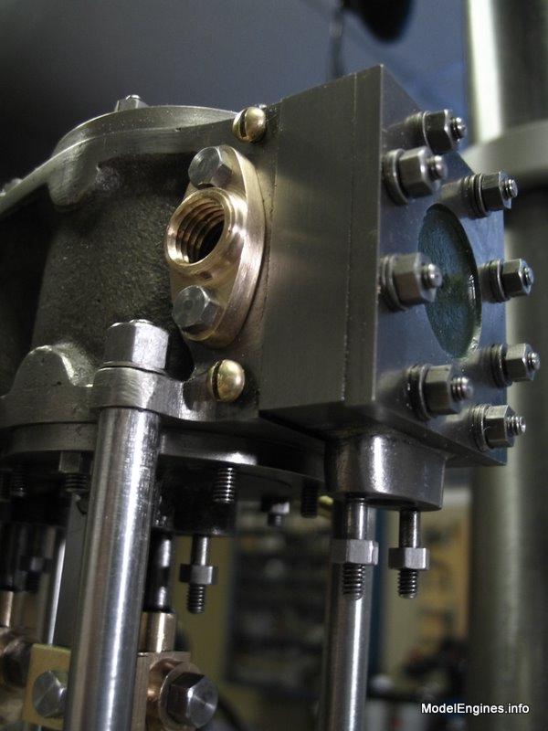
Wondering about the double washers under the valve cover nuts? - they are temporary
(the gaskets are not yet installed between the cylinder block, steam chests and covers
so the extra washers make up for the equivalent thickness of the gaskets)
The revealled edge of the valve chest (beside the brass slot screw) is per the drawings
- it will mate flush with the lagging sheet which covers the cylinder block, but not the steam chest

Making the Exchange Pipe
(if you already knew that,
then you probably wish to skip this part and I'll meet you below at the next photo)
However if you think that a pipe is just a pipe, perhaps it is time for a few words about compound engines :-)
On the main page dedicated to this engine I mentioned that it was a "receiver compound"
engine. (there are two other types - a tandem compound and a Woolfe compound which use two cylinders in line on a single piston rod
.....both of these engines only provide torque twice
per revolution compared to four in a reciever compound engine)
A receiver or angle compound either has the cranks for the two cylinders set a quarter turn
(90°) apart or the cylinders themselves are perpendicular to each other (these can be a 90° V-configuration, or one vertical and one horizontal cylinder). Whatever the method the result is the same - when either piston is at the
midpoint of its travel, the other piston will be at the top or the bottom. This provides the steady torque of
four power strokes covering a full revolution - a trait which is common to most later simple or compound twin steam engines.
However
it also means that a receiver compound engine is more than just a single cylinder engine simply being fed by a pipe from another one-cylinder engine's exhaust. Due to the timing difference, the total volume of the receiver becomes important since it stores steam at a varying pressure throughout each revolution. The relationship of the pressures in the receiver, the HP exhaust and the LP intake becomes somewhat complicated. It has everything to do with how the engine responds to different shaft loads and the distribution of torque throughout the crankshaft rotation at different degrees of steam admission cutoff in the cylinders.
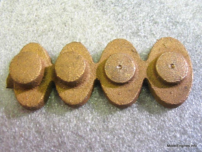
I will start by machining the two flanges for the exhange pipe

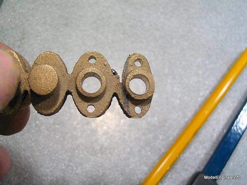
The two castings on the left will become valve rod glands - the others will become the flanges
I drilled completely through with the center drill

Just making sure!
These will be the matching pair of flanges for the exchange pipe
Time to clean off the bottoms with the large surface mill hanging ominously overhead

OK - I couldn't resist trying this...
This method is not advisable unless you are confident that it is safe
A 6" grinder wheel removes metal very quickly and great care is needed
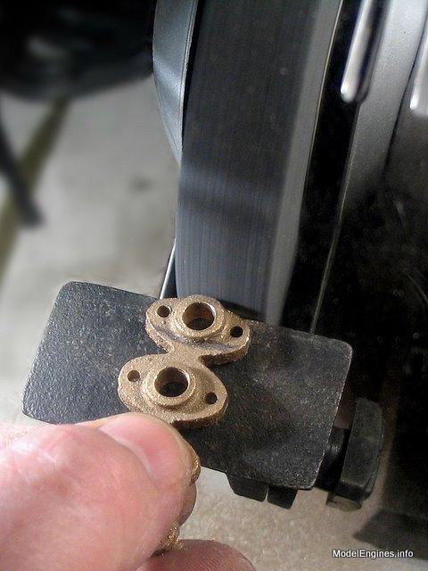
Make no mistake -
this photo was taken through the Lexan wheel guard,
I was wearing a face shield and had a good grip on the four-flange casting.
It did save me a lot of filing...

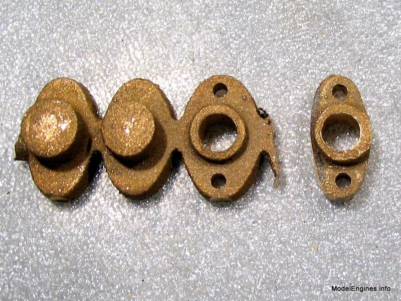
In a further attempt to cut down on filing I cut it very close to final size with a junior hacksaw
Now the side of the next flange can be ground
This is a stub mandrel - turned to size in the chuck and very slightly tapered
to allow the flanges to press on perfectly in line with the lathe axis
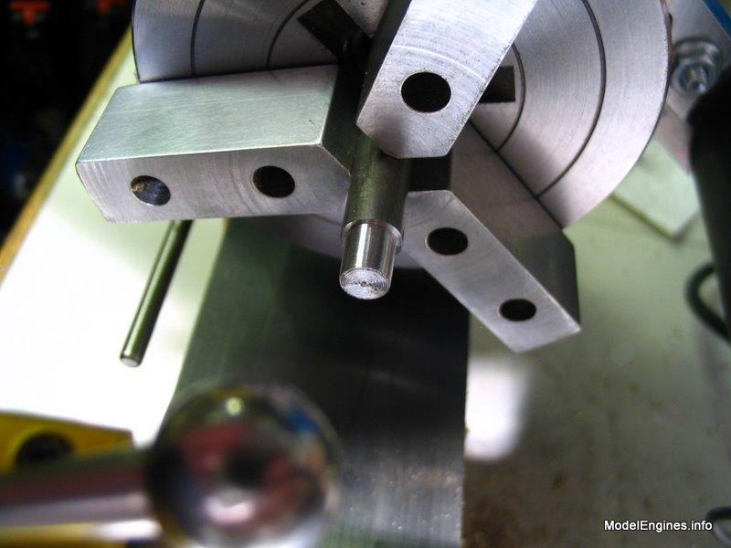
Ready to finish the top surfaces
Note that the perimeter edge of the flange will be finished by hand later

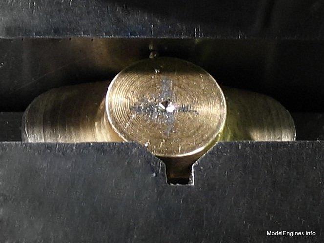
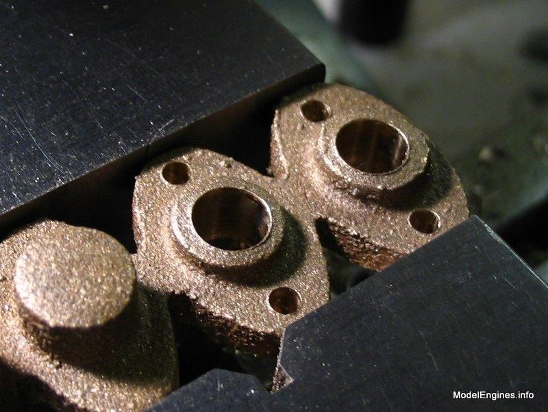
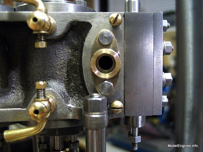
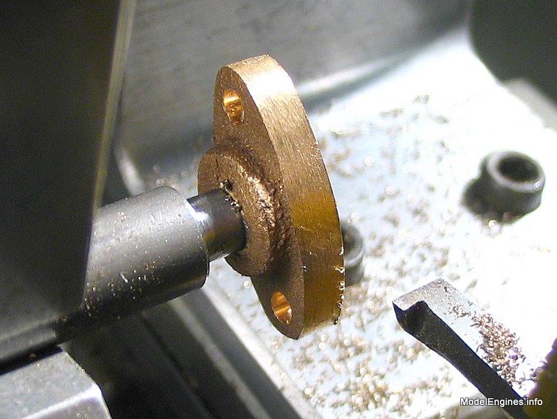
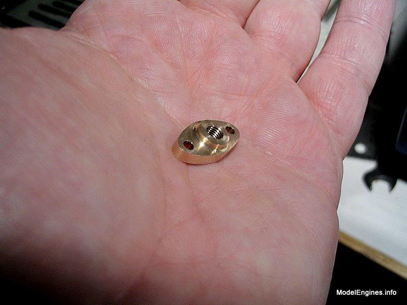
Test fitting - it looks similar to the LP exhaust flange but is smaller and not threaded

You can see the smaller hole in the cast iron surface of the cylinder block through the hole in the flange. When the thick-wall copper pipe is brazed to the flange, the end of the tube will butt against the exposed cast iron of the steam chest, with the openings of each matching almost exactly.
I don't have the camera precisely lined up for this photo, but in fact the holes are concentric!
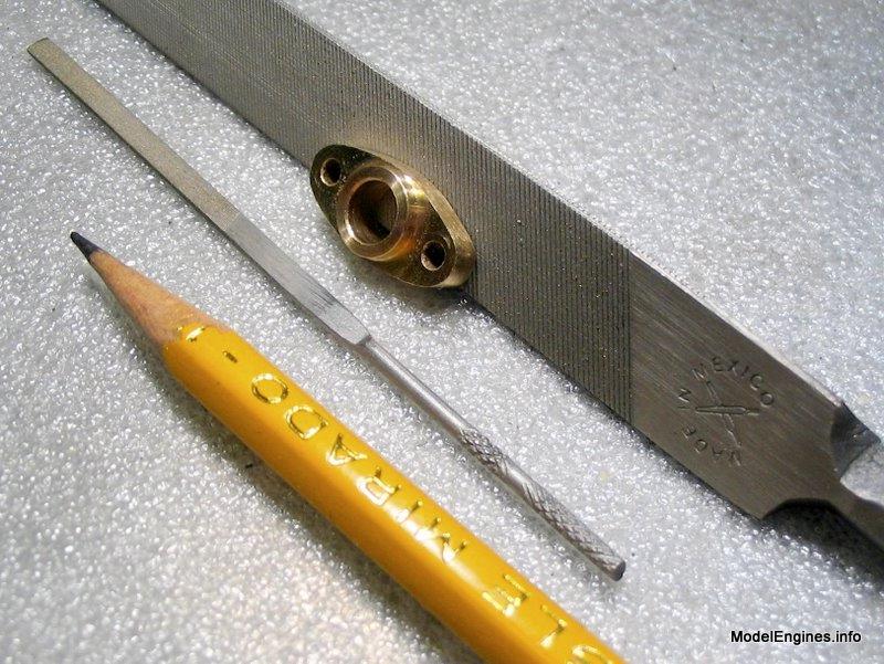
Here are the files that will do the job:
The one on the right is a parallel edge, triangular Nicholson machete file. It has enough weight to stay level without rounding the edges excessively. The little file is much smalller than it appears - it is about half the size of the typical small files sold in most hobby shops.
The pipe is 1/4" OD - I will anneal it, then bend it around a homemade former.
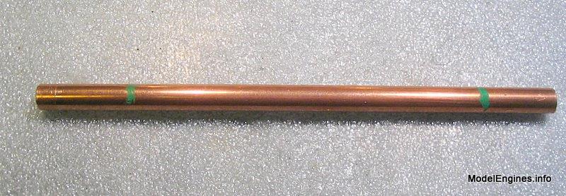
The green marks indicate the centers of the bends - one short section is 1/8" longer than the other to compensate for the smaller width at the HP end of the cylinder block
This aluminum former has been around my shop for years

Ready to bend the first few degrees
The pipe is heated cherry red then bent when cold
Repeated heatings were necessary

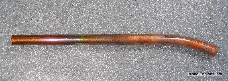
Almost completed on this end
It is nice thick tubing and holds its cross section shape well under bending
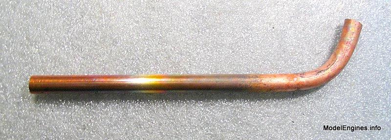
Once the other end is bent, the ends can be shortened somewhat

Bending essentially complete except for some minor adjustments

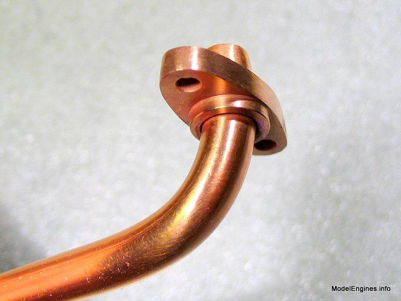
I used a countersink to provide a solder recess around the pipe on the flange face

Fluxed and ready for silver brazing

The brazing finished on the assembly
View from the "visible" side
Up close before trimming and polishing
After it is cut off and made flush, the thickness of the pipe wall will add to the surface area of the flange face
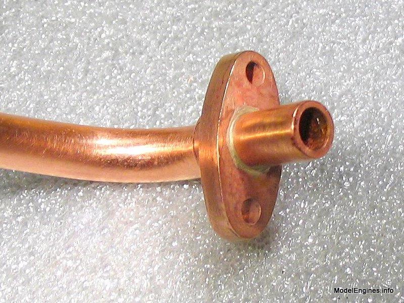
The ends were cut off nearly flush using a Junior Hacksaw
After facing with a file, the silver alloy ring and pipe wall are clearly visible in this view
The resultant extra area of mating surface will help the gasket do its job
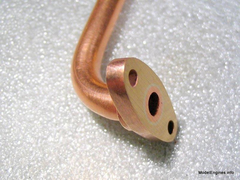
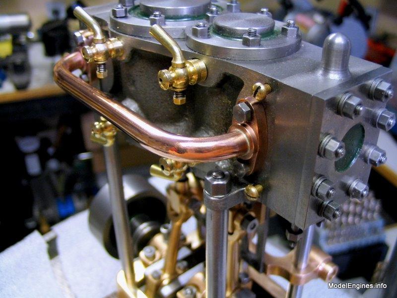
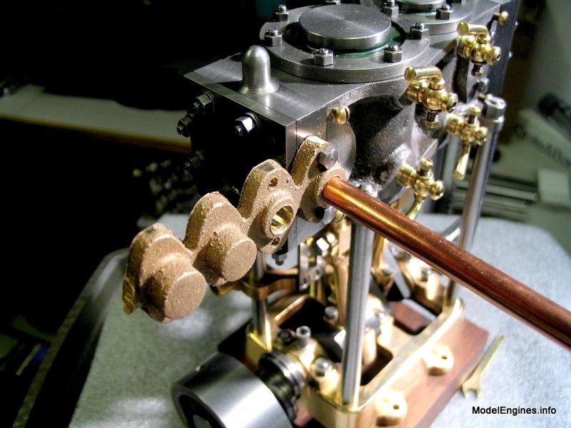
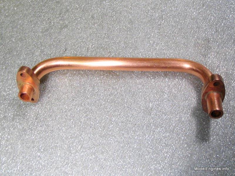
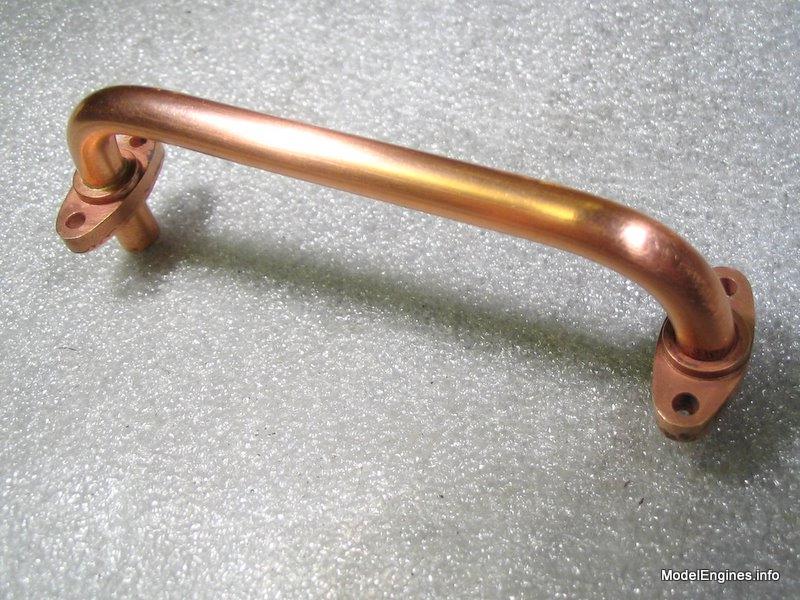
The completed exchange pipe assembly after a light polishing

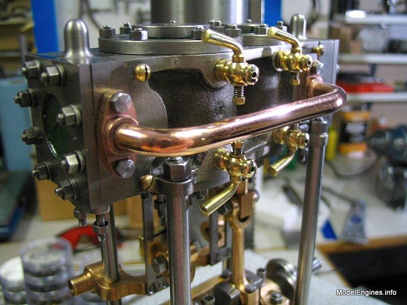
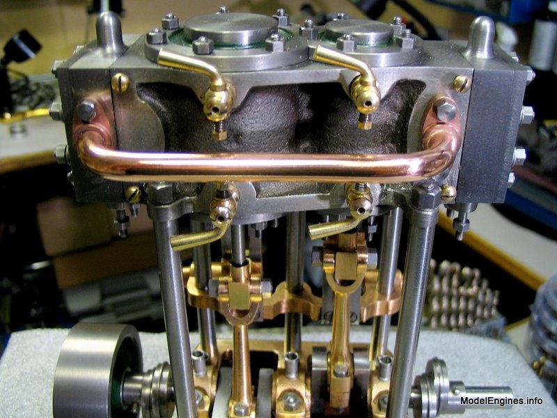
Three images of the pipe in position follow:

The Final Flange
H.P flange for the main steam supply from the boiler

This is the smallest diameter pipe connection. It also operates at the highest pressure.
All the steam which opeates this engine will pass through this location.
There is little that needs to be said about the construction of this component
- it is simply a smaller brother to the exhaust flange at the first of this page.


It really is quite a small piece
The degree of steam expansion that takes place through the engine is evident
by comparing the relative sizes of the inlet on the left and outlet (foreground).

High pressure end

Low pressure end

The Packing Box Glands
The bottom cylinder covers showing the piston rod glands
.JPG)
Yes I know one of the cylinder nuts is on upside down - I will correct that!
Once again - this is how I trimmed these castings - it worked well for me
but I am not suggesting this is how someone else should do it (there's always a file)
.JPG)
Ah! - there's nothing like a Black & White photo
.JPG)
I made a 7/32" reamer to suit the piston rod holes
(I already had a 1/8" reamer on hand for the valve rod glands)
.JPG)
Cross marks are from the coarse grinding wheel used to rough out the shape
The edges are keen - honed on a diamond coated block
.JPG)
In any case, being able to quickly make reamers saves a lot of time and cash
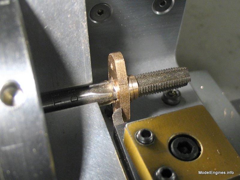
I centre-drilled the end of the shank for future use with the tailstock centre
.JPG)
Ready to bring the hole out to 7/32"
.JPG)
A freshly-turned tapered stub mandrel from 12l14 steel to suit the bore
.JPG)
This stub is the 1/8" stub for the valve rods - it was turned down from the 7/32" version
A valve rod gland casting pushed onto the stub - ready to turn
.JPG)
Stubs are totally acurate, no matter what chuck is used, because they are turned to size in situ.
(obviously they cannot be re-used once removed from their setting in the chuck)
Both sides of the piece can be faced while on the mandrel
.JPG)
Valve rod glands
.JPG)
Checking concentricity of the LP valve gland prior to edge finishing
.JPG)
The gland on the other end (HP) is already finished
.JPG)
Piston rod glands before drilling for studs
.JPG)
The four completed glands
.JPG)
The next stage is the construction and fitting of the components for the Stephenson Link reversing gear.
Castings, Materials and Fastenings
Soleplate
Cylinder Block
Top Covers
Bottom Cylinder Covers
Steam Chests
Crosshead Guides and Bracket
Crankshaft
Eccentrics
Flywheel
Connecting Rods and Crossheads
Main Bearings
Pistons
Fittings: Oil Cups
Fittings: Drain Cocks
Fittings: Exchange Pipe, Flanges and Glands (this page)
Stephenson Link Reversing Gear
Completing and Erecting the Compound Launch Engine
or
Compound Launch main page
Main website home page ModelEngines.info
![]()
(c) John R. Bentley 2011.