
John R. Bentley 2011.
Completing the Reversing Gear (page 5):
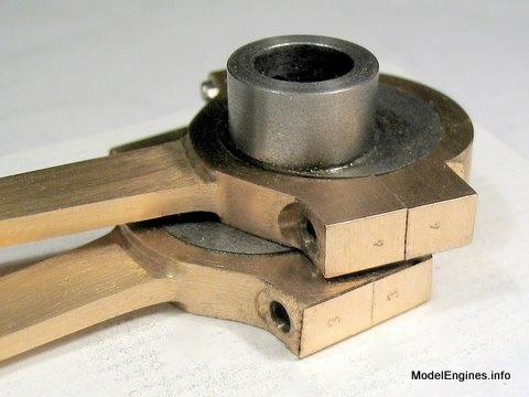
The eccentric straps for the Compound Launch engine are made integral with the rods. They are machined from gunmetal castings. There are four identical units required - one for each direction per cylinder. There are two modifications that might be nice - threading the holes in the bottom pieces of the straps instead of drilling 7BA clearance holes ...and reversing the relative positions of the tapped holes and clearance holes at the top of two of the the rods. The first change would allow the nuts to act as locknuts and ensure the straps don't come loose in operation. The modification to the top of the rods is purely cosmetic as it will allow both rods to display either both nuts or both hex bolt heads where they connect to the bottoms of the curved expansion links.
The four raw castings
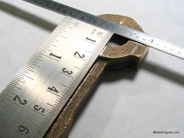
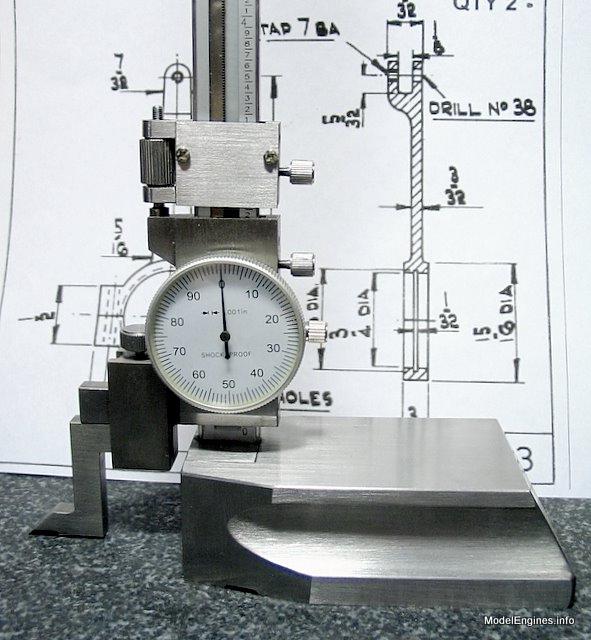
The all-important dimension is the distance between the centerline of the big hole and the pivot hole at the top of the rod. Two inches is the distance and I used a height gauge and granite surface plate to make certain I had it correct. My plate is accurate to one ten-thousandth of an inch.
Engine Construction Pages:
the Eccentric Straps/Rods
- for the Stuart Compound Launch Engine -

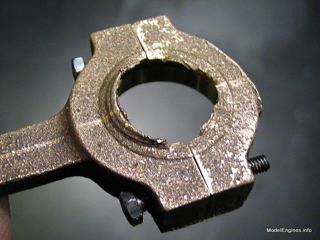
The first of four bronze eccentric straps which will be coupled to the expansion links

Gunmetal is a soft and bendable material - it's always wise to check for things like this
One way to derive the bisecting line
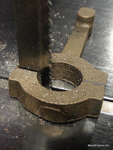
Cutting with the Craftex 4x6 bandsaw in the vertical configuration
After smoothing the cut surfaces

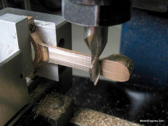
The eccentric's long rod is inverted in this setup

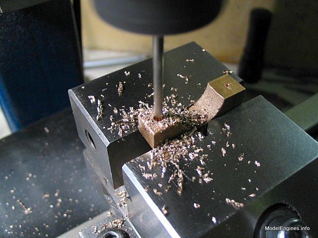
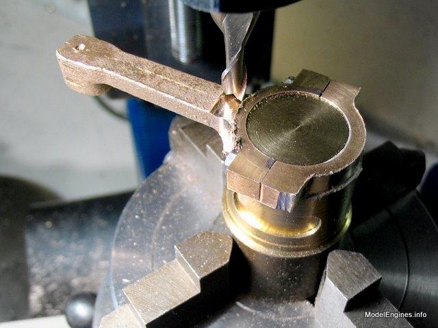
Centre-drilling for the bolt holes
The top portion of the strap (shown) being drilled with a No.40 bit
The bottom half was drilled smaller to allow threading the holes (my modification)

Hand tapping 7BA
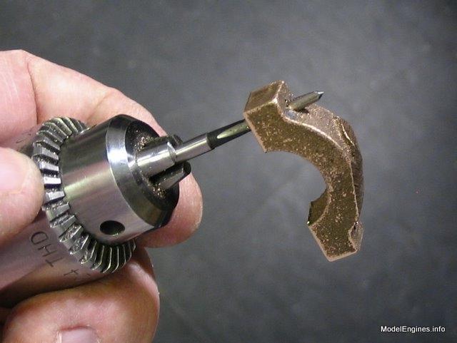
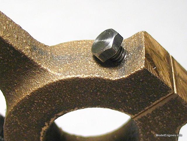
Testing the hex screws

(no, I haven't slipped a cog - to be accurate, a SCREW is threaded up to the head and a BOLT is threaded only at the bottom end)
It is clear that at some point these will need to be spotfaced
These temporary short screws will be needed when the bottom is machined

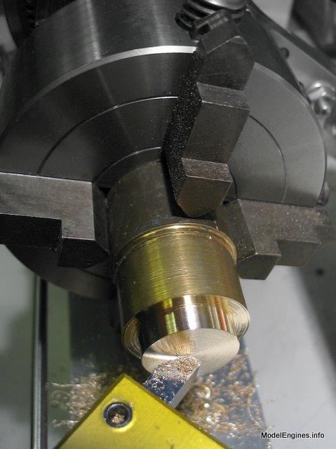
However first things first - the large hole should be bored
Bored to fit the sheave - 0.750"

Obviously this is a later effort (No.3) - Note the use of a slotted hex head screw

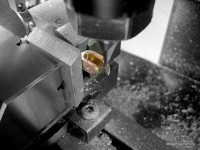
The next job is to cut the positioning groove with this cutter
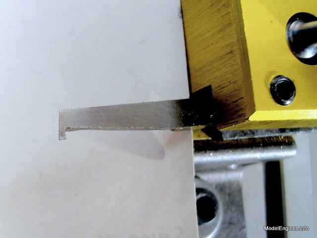
It is difficult to see the operation...
I have found an unbreakable Plexiglas mirror is good for just this sort of situation

Obviously it is nearly impossible to see the cutting surface without the mirror

(an option would be to use the Taig rear-mounted toolpost with the tool upside down cutting on the other side of the hole)
The finished groove is visible inside the rotating bore
The back side - boring completely through was restricted by the chuck jaws
The casting is thicker than the final part, so the extra metal will be removed when this side is face-turned
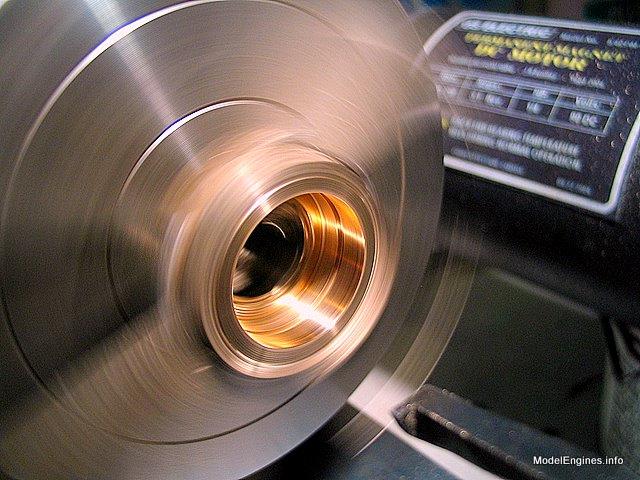
Setting up for lapping the strap on the eccentric sheave using the Taig lathe

I used valve grinding compound and oil to accomplish the lapping process

That's the inside job completed - note the sacrificial bolts looking rather haggard
A view of the inside at this point
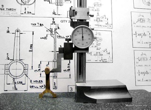
There's nothing like fancy instruments - if you use them correctly...
Just on a whim I grabbed a lowly ruler, only to find my mark off by a full 3/32"! - that's 938 of those ten-thousandths!

The moral here is that it is easier to go astray with more complex tools
(this simple ruler would have measured this dimension with ample accuracy for this purpose)
The root of the problem of course was that I forgot to zero the height gauge
against the granite surface in this fashion before making the measurement
I used a 3/16" endmill to spotface the strap for the bolt heads

A homemade spotface tool with pilot guide might be a better option
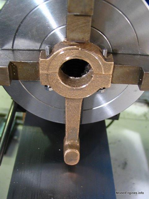
It is about time to profile the outside of the strap

Turning a short stub mandrel for the strap in the Taig 4-jaw chuck
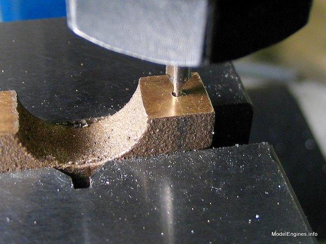
Using the stub and chuck on the rotary table to hold the strap while profiling the outer portion
Judicious use of packing to allow milling with the side of an endmill

I found the bottoms of endmills almost hopeless in machining gunmetal
- however the sides vorked quite well
Drilled clear on one side - tapped on the other
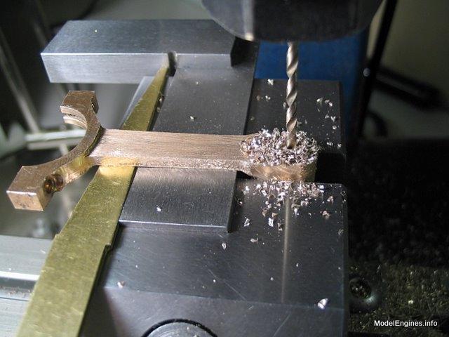
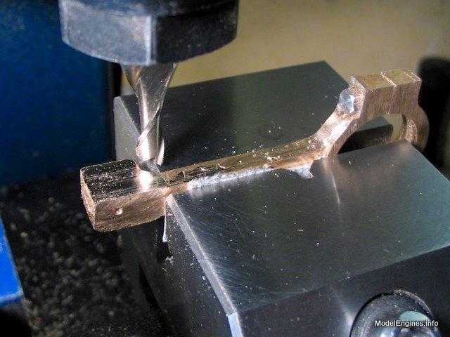
Profiling the rod edges and top clevis rod end
Prior to forming the clevis end

One way to cut the slot in the clevis
On the last three castings I used a 1/8" slitting saw in the mill to do this job

Spotfacing the bottom with an endmill - the sacrificial screws are in position

Finally! - milling the flat sides of the strap since it will no longer need to be gripped in the vise.

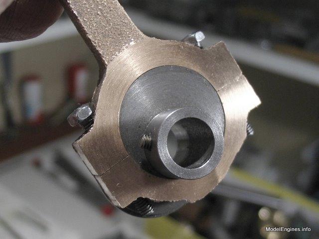
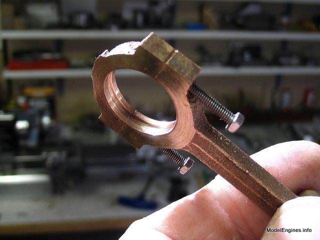
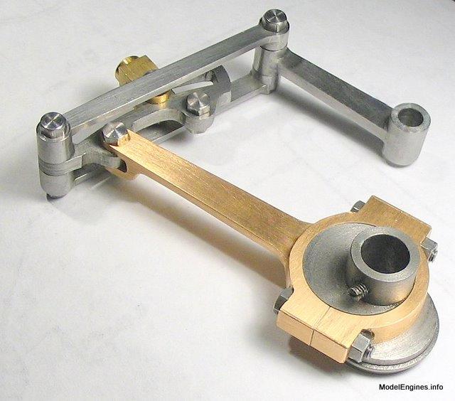
The completed eccentric strap/rod attached to one of the expansion links
The other three strap castings - split and temporarily numbered - ready for drilling and machining

I used large number stamps so they would be easily visible during construction
(these help in keeping the two halves of each together and properly orientied)
Of course I chose smaller numbers for permanant use
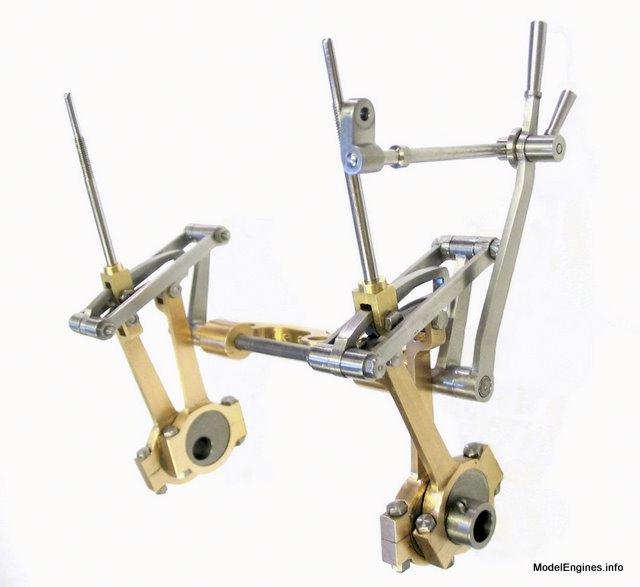
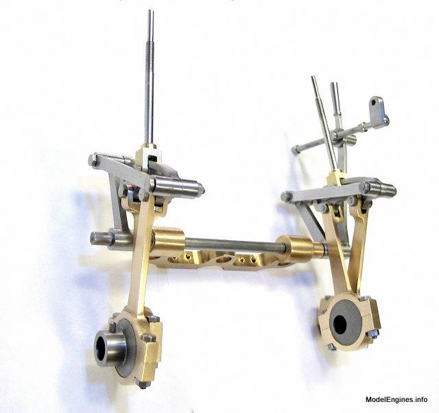
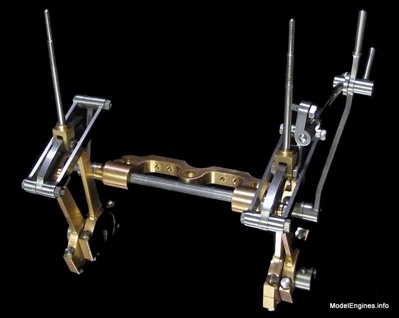
I will include a short series of views showing the completed (but unpinned) linkage assembly below:
An overview of the reversing gear from the hand lever side
The other end - in my case it will be situated at the LP side of the engine
A view of the complete linkage sitting on its side

The plans suggest pinning the two connecting arms and the reversing lever to the shaft -
I would like at least one pin easily removable so the shaft can be readily extracted.
The completed Stephenson Link Reversing Gear
Castings, Materials and Fastenings
Soleplate
Cylinder Block
Top Covers
Bottom Cylinder Covers
Steam Chests
Crosshead Guides and Bracket
Crankshaft
Eccentrics
Flywheel
Connecting Rods and Crossheads
Main Bearings
Pistons
Fittings: Oil Cups
Fittings: Drain Cocks
Fittings: Exchange Pipe, Flanges and Glands
Stephenson Link Reversing Gear (page 1)
Stephenson Link Reversing Gear (page 2)
Stephenson Link Reversing Gear (page 3)
Stephenson Link Reversing Gear (page 4)
Stephenson Link Reversing Gear (page 5) - this page
Completing and Erecting the Compound Launch Engine
or
Compound Launch main page
Main website home page ModelEngines.info
![]()
© John R. Bentley 2011.