
John R. Bentley 2011.
Constructing the Reversing Gear (page 2):
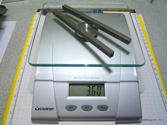
This page covers machining the four drag links from two bars of steel. Each pair surrounds a curved expansion link so that those links can be moved in unison when the reversing shaft is rotated.
It is interesting that these two bars will be reduced in weight from 3.6 ounces to 0.4 ounces after machining into the four drag links
Engine Construction Pages:
the Drag Links
- for the Stuart Compound Launch Engine -
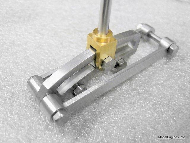
A curved expansion link flanked by two drag links
If you are not familiar with it, the operation of the Stephenson Link can be easily understood by considering these points:
A single eccentric at 90° to the crank, when coupled to the valve rod, will allow a single cylinder engine to function in one direction. Positioning that eccentric 90° to the other side of the crank will cause the engine to rotate in the opposite direction. Installing two eccentrics - one at each position will offer a choice.
The curved expansion link simply couples the two ends of the eccentric rods to the valve rod. When the expansion link is in the mid-position the two rods simply jiggle out-of-phase and their combined motion imparted to the valve is cancelled - the engine is stopped.
However when the expansion link is moved to either end, the motion from the nearest eccentric rod is passed along to the valve rod causing the engine to turn in the direction associated with that eccentric. (when this happens the other eccentric rod only moves the bottom of the curved link sideways, having no effect on the valve rod's vertical travel)
In a two cylinder engine such as this one, this system is simply duplicated for each cylinder and the two expansion links are caused to be moved in unison by hand-twisting a common horizontal shaft.
To explain in the simplest of terms: the curved link simply selects the vertical motion from either the forward or reverse eccentric and applies that motion to the valve rod.
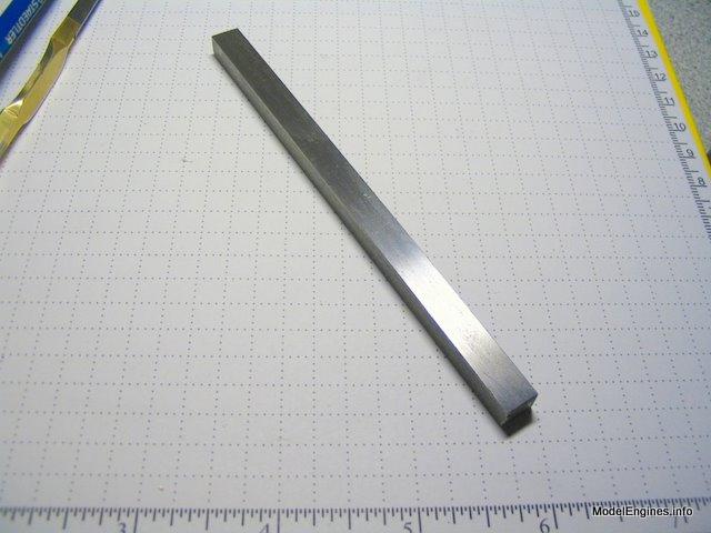
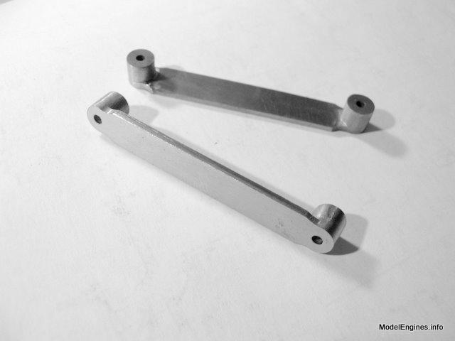
The bars are 5/16" square
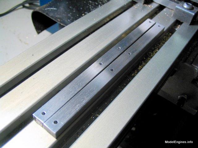
Drilling the holes for each end of the four bars

Ready to start...
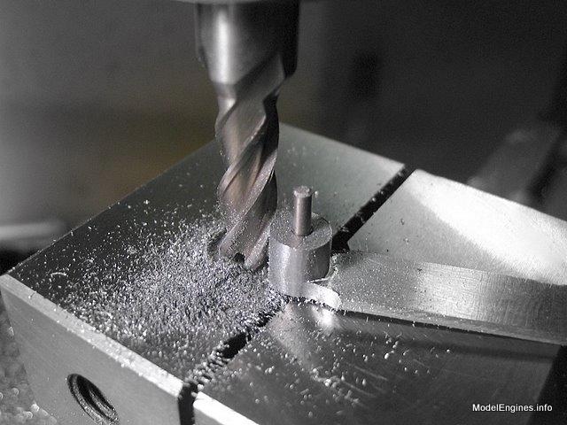
The metal between the end hubs must be removed

The next time I will use a smaller endmill
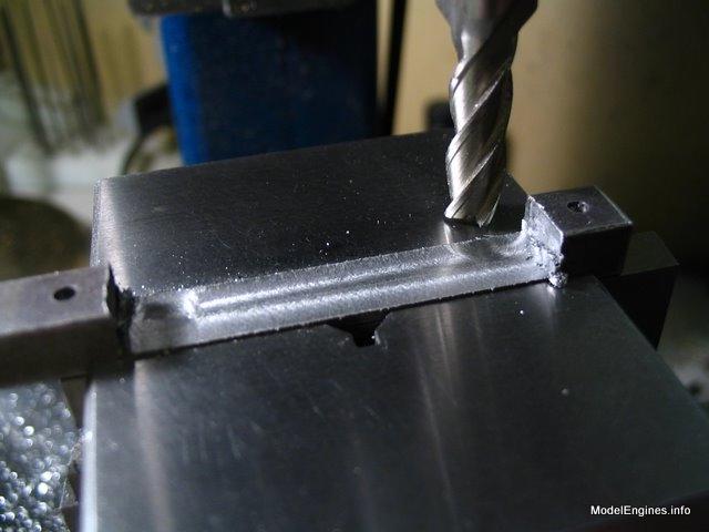
More metal gone than remaining
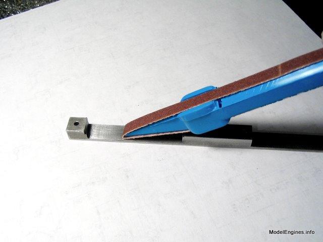
This surface will show on the finished part so some emery cloth was enlisted
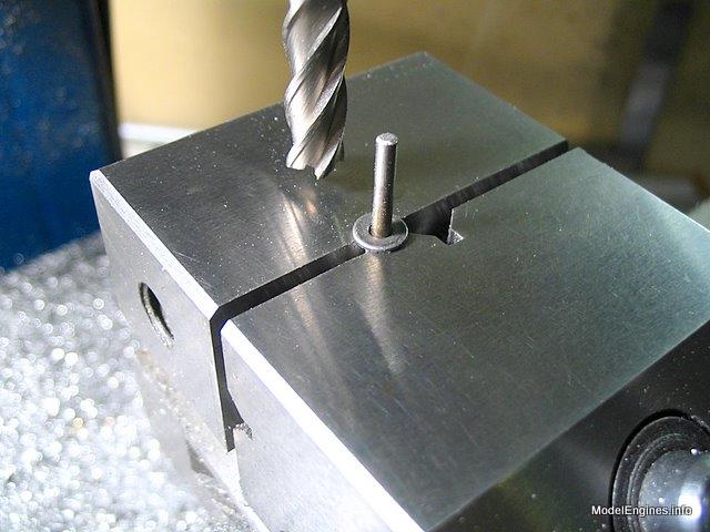
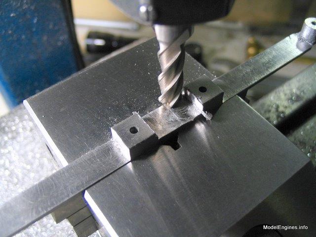
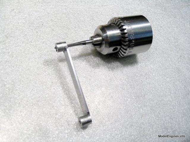
Setting a pin for circular milling
After milling the top part of a hub

Completing the hub
Two end hubs finished

Clearing out the space between the two components
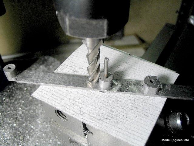
Rough milling the other two hubs

Finishing around the same pin as used for the ends
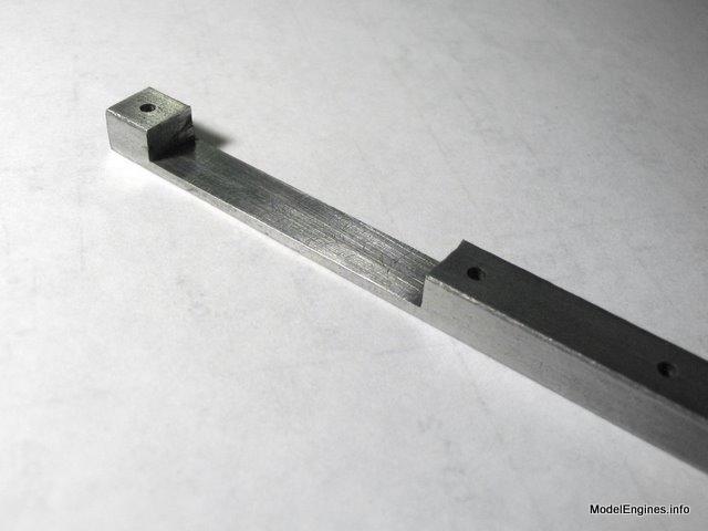
A view of the two embryo links in one bar
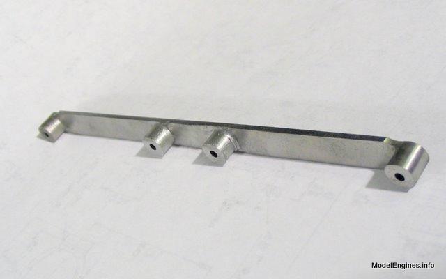
The flat sections will be reduced in width later
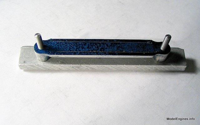
By threading the holes on the two inside links, the nuts will act as locknuts. My previous engine sometimes drops a nut in action and I am determined to prevent it by mechanical means without the use of chemical threadlockers.
Tapping the holes 7BA
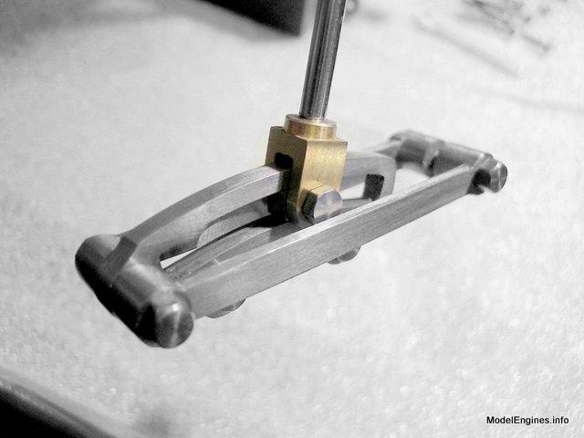
Setting the piece in a jig for milling the profile
This will bring the drag links to final size

An assembly of two drag links with an expansion link in the middle
Next Page
Making the connecting links
Castings, Materials and Fastenings
Soleplate
Cylinder Block
Top Covers
Bottom Cylinder Covers
Steam Chests
Crosshead Guides and Bracket
Crankshaft
Eccentrics
Flywheel
Connecting Rods and Crossheads
Main Bearings
Pistons
Fittings: Oil Cups
Fittings: Drain Cocks
Fittings: Exchange Pipe, Flanges and Glands
Stephenson Link Reversing Gear (page 1)
Stephenson Link Reversing Gear (page 2) - this page
Stephenson Link Reversing Gear (page 3)
Stephenson Link Reversing Gear (page 4)
Stephenson Link Reversing Gear (page 5)
Completing and Erecting the Compound Launch Engine
or
Compound Launch main page
Main website home page ModelEngines.info
![]()
© John R. Bentley 2011.